Storage 03 section d.
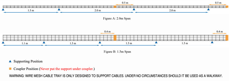
Cable ladder support distance.
Install cable tray support using a pre fabricated flange or gi channel.
As the cost of structural steel continues to increase the impact of reducing the quantity of supports on a project can offset the cost of the cable ladder system all together.
Introduction 02 section b.
Installation 03 section d 1.
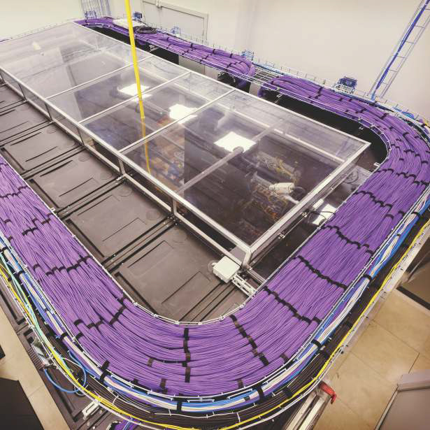
Below drawing shows how to install cable tray and its support system.
Ancillary products accessories.
This cable tray support system drawing has isometric view and cross sectional view.
Straight length installation 16 section d 4.
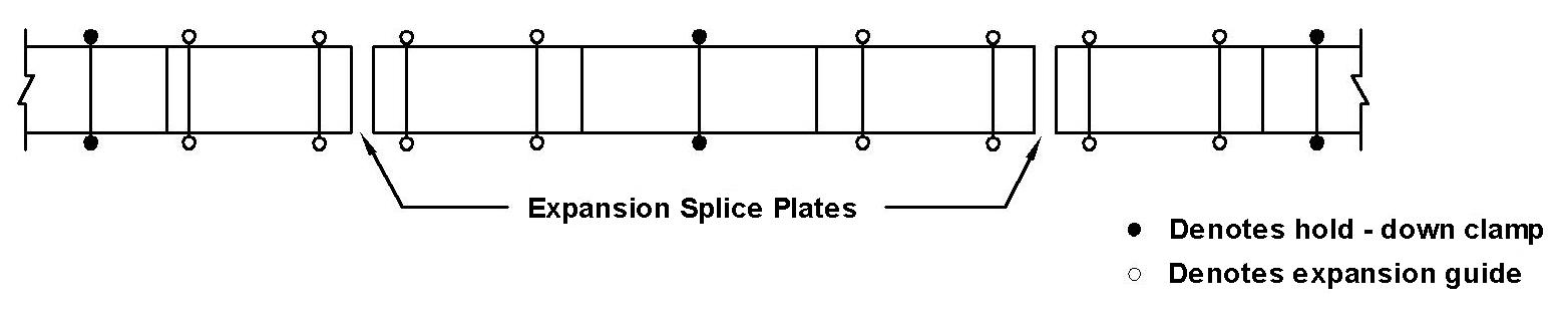
Field modifications 25 section d 6.
Sa 08 8360 4550 nsw 02 8783 7555.
Installation of cable 41 2 11 preparation 41 2 12 wiring regulations 41 2 13 power cables 41 2 14.
The size length and intervals of the support to be as per the specification standards.
Cable supports should be applied either side of the bend.
Support of cable tray and ladder is typically done in the same fashion as us installations.
Receiving and unloading 03 section c.
Installation of support structure 09 section d 3.
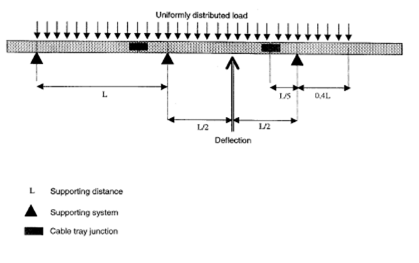
For flexible systems where the cable is not directly fixed to the support system for example a j hanger installation calculations need to be undertaken to determine the required distance between the cable support positions to achieve a set deflection off set.
Support points are often trapezes suspended from threaded rod cantilever brackets or other strut systems.
2 3 support systems 18 2 4 straight cable ladder and cable tray lengths 29 2 5 coupler types refer to manufacturer s literature 32 2 6 fixings 36 2 7 fittings 36 2 8 accessories 39 2 9 site modification 39 2 10 earth protection and emc 40 2b.
In the case of electrical products such as cable tray or ladder which are load rated in kilograms per metre the span is the distance between support points separate from the overall length of the tray or ladder itself.
The support system for cabling and equipment is a vital component of a properly designed data communications system.
The acceptance and use of the eia tia 569 commercial building standard for telecommunications pathways and spaces by architects and engineers has proven the importance of a carefully designed and maintained cable support system.
1 table of contents 02 section a.
Following are the steps to be done for laying cables on wall mounted cable tray.
Fittings installation 23 section d 5.
Learn how to reduce structural supports in cable ladder installations.
Common tools for installation 04 section d 2.
Support load calculation per iec 61537 one or more spans iec 61537 7 3i for installations with more than one span it is important to notice that the loading capacity is not the same form one end to the other.